The JTAG (Join Test Action Group) IEEE 1149.1 standard was published in 1990. This first standard was developed by a group of over 200 major electronics manufacturers. It has been conceived to provide common rules of testability throughout the product life cycle on one hand. On the other hand, the standard bring an answer to the intensive use of BGA (Ball Grid array) packages, multi-layers boards and the overall scaling law in geometry. As a main result this standard enable to detect the majority of manufacturing faults in circuit boards, like solder joints, boards connections, opens, shorts and stuck-at faults are detected.
Overview
JTAG is also widely used as an IC debug port in most of the processors used on the market. This enable to perform functional tests on board, to integrate debuggers in the JTAG process flow and to increase the overall test coverage. Typical devices that incorporate boundary-scan technology include CPLDs, FPGAs, Microprocessors, DSPs, ASICs, bus logic, SERDES, telecom encoders, PHYs and Bridges (PCI/PCIe).
How it works
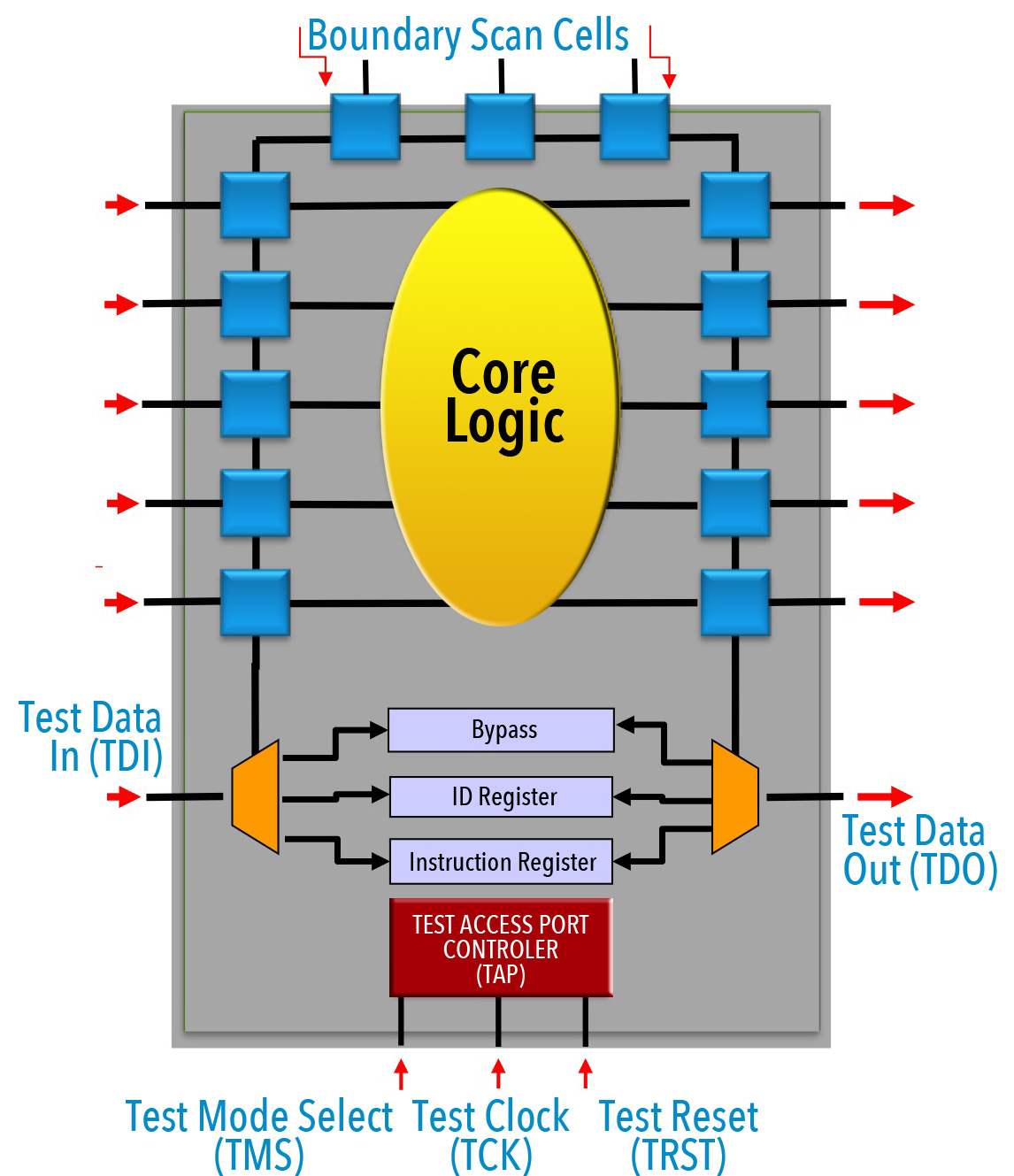
The major part of digital, but also some analog components integrates as a native infrastructure the boundary scan architecture. It consists of a TAP (Test Access Port) and boundary scan registers linked altogether in a serial mode. Four to five pins (signals) are dedicated to the monitoring of the test access port which are:
• TCK •
(Test Clock)
• TDI •
(Test Data In)
• TDO •
(Test Data Out)
• TMS •
(Test Mode Select)
• TRST •
(Test Logic Reset) (optionnel).


To activate the boundary-scan logic, simply pulse TCK while toggling TMS as specified in the TAP state machine map. Once activated, boundary-scan logic controls the device's pins while isolating the primary core functions of the device.
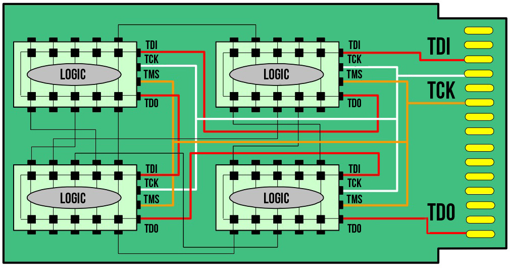
The figure here below shows an implementation of a JTAG test infrastructure within a PCB. it is common to connect the devices in a serial (daisy chain) formation so that the first device's TDO connects to the next device’s TDI (and so on) to form a so-called scan chain.
A number of device manufacturers embracing boundary-scan technology are Intel, Analog Devices, ARM, Freescale, NXP, PLX, ST, TI, Renesas, Xilinx, Altera, Lattice, Broadcom and Actel among others.
The standards corner
Description:
IEEE Std. 1149.1-1990, defines circuitry that may be built into an integrated circuit to assist in the test, maintenance, and support of assembled printed circuit boards. The circuitry includes a standard interface through which instructions and test data are communicated. A set of test features is defined, including a boundary-scan register, such that the component is able to respond to a minimum set of instructions designed to assist with testing of assembled printed circuit boards.
www.standards.ieee.org/findstds/standard/1149.1-1990.html
This standard was supplement over the years with:
1149.1a-1993 - Supplement to Standard Test Access Port (1149.1)
1149.1b-1994 - Supplement to Standard Test Access Port (1149.1a)
1149.1-2001 Supplement to Standard Test Access Port (1149.1b)
Status (active standard)
Description:
Circuitry that may be built into an integrated circuit to assist in the test, maintenance and support of assembled printed circuit boards and the test of internal circuits is defined. The circuitry includes a standard interface through which instructions and test data are communicated. A set of test features is defined, including a boundary-scan register, such that the component is able Circuitry that may be built into an integrated circuit to assist in the test, maintenance and support of assembled printed circuit boards and the test of internal circuits is defined. The circuitry includes a standard interface through which instructions and test data are communicated. A set of test features is defined, including a boundary-scan register, such that the component is able to respond to a minimum set of instructions designed to assist with testing of assembled printed circuit boards. Also, a language is defined that allows rigorous structural description of the component-specific aspects of such testability features, and a second language is defined that allows rigorous procedural description of how the testability features may be used.
http://standards.ieee.org/findstds/standard/1149.1-2013.html
Status (active standard)
Description:
The testability structure for digital circuits described in IEEE Std 1149.1-2001 has been extended to provide similar facilities for mixed-signal circuits. The architecture is described, together with the means of control of and access to, both analog and digital test data. Sample implementation and application details (which are not part of the standard) are included for illustration. Also, extensions to the standard BSDL are defined that allow description of key component-specific aspects of such testability features.
http://standards.ieee.org/findstds/standard/1149.4-2010.html
Status (active standard)
Description:
This standard defines test methodologies for high-speed buses in the one to 10 gigabits-per-second (Gbps) range that feature serial AC-coupled chip-to-chip interconnects and/or differential signaling, such as Gigabit Ethernet, Fibre Channel and others. This standard augments IEEE Std 1149.1 to improve the ability for testing differential and/or ac-coupled interconnections between integrated circuits on circuit boards and systems.
http://standards.ieee.org/findstds/standard/1149.6-2003.html
Status (active standard)
Description:
IEEE 1149.7 extends the test and debug capabilities of the IEEE 1149.1 TAP to complex devices like system-on-chip (SOC), system-in-package (SIP) and other multi-core or multi-die 3D devices. This specification describes circuitry that may be added to an integrated circuit to provide access to on-chip test access ports (TAPs) specified by IEEE Std 1149.1-2001. The circuitry uses IEEE 1149.1-2001 as its foundation, providing complete backward compatibility, while aggressively adding features to support test and applications debug. It defines six classes of 1149.7 test access ports (TAP.7s), T0 - T5, with each class providing incremental capability, building upon that of the lower-level classes. Class T0 provides the behavior specified by 1149.1 from start-up when there are multiple on-chip TAPs. Class T1 adds common debug functions and features to minimize power consumption. Class T2 adds operating modes that maximize scan performance. It also provides an optional hot-connection capability to prevent system corruption when a connection is made to a powered system
http://standards.ieee.org/findstds/standard/1149.7-2009.html
Status (active standard)
Description:
Extensions to IEEE Std 1149.1(TM) that define the boundary-scan structures and methods required to facilitate boundary-scan-based stimulus of interconnections to passive and/or active components are specified. Such networks are not adequately addressed by existing standards, including those networks that are ac-coupled or differential. The selective ac stimulus generation enabled by this standard, when combined with non-contact signal sensing, will allow testing of the connections between devices adhering to this standard and circuit elements such as series components, sockets, connectors, and integrated circuits (ICs) that do not implement IEEE Std 1149.1. This standard also specifies Boundary-Scan Description Language (BSDL) extensions to IEEE Std 1149.1 required to describe and support the new structures and methods.
http://standards.ieee.org/findstds/standard/1149.8.1-2012.html
Status: (active standard)
Description:
This standard defines a mechanism for the test of core designs within a system on chip (SoC). This mechanism constitutes a hardware architecture and leverages the core test language (CTL) to facilitate communication between core designers and core integrators.
http://standards.ieee.org/findstds/standard/1500-2005.html
Status (Withdrawn standard)
Description:
IEEE 1532-2002 is a standard for in-system configuration of programmable components such as complex programmable logic device (CPLD), erasable programmable logic device (EPLD), and field programmable gate arrays (FPGA). The scope of IEEE Standard 1532 includes a series of mandatory and optional programming instructions and associated data registers that define a standard methodology for accessing and configuring programmable devices. These additional registers and instructions extend the capabilities of devices that comply with the IEEE Standard 1149.1, enabling the test access port to be used for configuration activities. A data description format and extensions to the boundary scan description language (BSDL) are also specified to provide for the development of standardized automation tools for device programming.
http://standards.ieee.org/findstds/standard/1532-2002.html
Status (active standard)
Description:
IEEE Std 1581 defines a low-cost method for testing the interconnection of discrete, complex memory integrated circuits (ICs) where additional pins for testing are not available and implementing boundary scan (IEEE Std 1149.1(TM)) is not feasible. This standard describes the implementation rules for the test logic and test mode access/exit methods in compliant ICs. The standard is limited to the behavioral description of the implementation and will not include the technical design for the test logic or test mode control circuitry.
http://standards.ieee.org/findstds/standard/1581-2011.html
Status (active standard)
Description:
A methodology for accessing instrumentation embedded within a semiconductor device, without defining the instruments or their features themselves, via the IEEE 1149.1(TM) test access port (TAP) and/or other signals, is described in this standard. The elements of the methodology include a hardware architecture for the on-chip network connecting the instruments to the chip pins, a hardware description language to describe this network, and a software language and protocol for communicating with the instruments via this network.
http://standards.ieee.org/findstds/standard/1687-2014.html
Further standards Active projects
Description:
The standard defines test access features for a die that enable the transportation of test stimuli and responses both for testing This die and its inter-die connections, as well as for testing OTHER DIES in the stack and their inter-die connections. The proposed standard is a 'die-centric' standard; it applies to a die that is intended to be part of a multi-die stack. The proposed standard defines die-level features, that, when compliant dies are brought together in a stack, comprise a stack-level architecture that enables transportation of control and data signals for the test of (1) intra-die circuitry and (2) inter-die interconnects in both (a) pre-stacking and (b) post-stacking situations, the latter for both partial and complete stacks in both pre-packaging, post-packaging, and board-level situations.
The proposed standard is based on and works with digital scan-based test access and should leverage existing test access ports (such as based on IEEE Std 1149.x) and on-chip design-for-test (such as IEEE Std 1500) and design-for-debug (IEEE P1687) infrastructure wherever applicable and appropriate. The proposed standard is 'die-centric', and hence does not aim at 'stack/product-centric' challenges, solutions, and standards, such as the inclusion of Boundary Scan features for board-level interconnect testing. However, the proposed standard should not prohibit the application of such solutions.
More information on http://standards.ieee.org/develop/project/1838.html
Introduction
A system-level JTAG initiative, called System JTAG (SJTAG) discussing a common set of problems associated with the extended test and configuration use of 1149.1 boundary-scan infrastructure within complex multi-board systems. The goal for SJTAG is: For all variants of XBST and EBST, to define the data contents and formats communicated between external Test Manager Platforms and internal Embedded Test Controllers,
This standard will develop a methodology for access to test, debug, instrument, configuration and/or programming, and emulation features (but not the features themselves) of devices via the IEEE 1149.1 Test Access Port (TAP) for the board and system (multiple board) domains.
The elements for this methodology include a description language(s) describing the structure of how various standards (e.g., 1149.4, 1149.6, 1532, P1687, 1581) and other access mechanisms leverage the IEEE 1149.1 defined TAP interface in the system; a description of data representation formats for test vectors, diagnostic analysis, and data logging; and software application programming interfaces (APIs) defining command primitives facilitating communications between functional command, control, and data modules of an SJTAG Test Manager application.
http://www.sjtag.org/
On the side of current and future manufacturing test solution strategies - iNEMI works on Boundary-scan and Built in Self-Test (BIST) technology integration for future standardization
Increasing product complexity and reduced test point access are driving a desire to increase use of technologies such as Boundary-Scan and BIST (Built-In-Self-Test) to improve test coverage. The International Electronics Manufacturing Initiative (iNEMI) investigates the gaps and ultimately driving for industry changes in the deployment of those technologies. The iNEMI Boundary-scan project team reviews current available test methods and strategy for testing the external memory devices and analyzed the gaps and opportunities and the opportunity of BIST technology for board level testing and the needs for standardization. The two projects clarify the requirements needed for the existing boundary-scan IEEE1149.1 standard and other industry standards to bridge the gap for lack of test point access and improved testability of products.
http://www.inemi.org/project-page/built-self-test-bist-program
